|
|
ROKR Vitascope Building kit for a real working antique film projector |
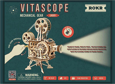 |
Build a real working antique film projector with
this interesting building kit from ROKR. The laser-cut parts are easy to
assemble using the enclosed step-by-step instruction book in English. The more
difficult steps can be viewed on a video by scanning a QR code. The kit comes complete with some tools, tape, sandpaper and wax. Batteries are not required; the power for the lighting is supplied by a small dynamo. Also glue is not necessary; the parts are fastened together with small wooden pins or by means of slotted connections. This results in an unexpectedly sturdy and reliable construction. |
 |
 |
|
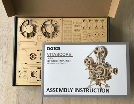
Immediately after opening the box you get a good impression
of the quality. Everything is neatly and precisely stored. The plywood sheets
are marked with letters, the parts marked with a corresponding letter and a
number, eg E15. The smaller parts are packed in small plastic bags. Ultimately, it turns out that many vulnerable parts have been duplicated so that the assembly can continue if something breaks or gets lost. |
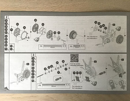
Assembly is described step by step with clear illustrations in the enclosed manual. It is recommended that at each step you first collect the necessary parts and then put them together. The manual explains very clearly how this should be done, but it is important to always look at it with great attention, because a mistake made cannot be corrected later or only with great effort. |
 |
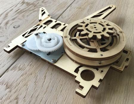 |
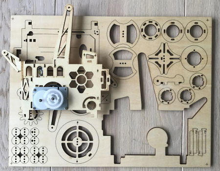
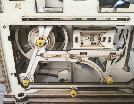
| When you remove the first part, one of the side walls of the projector, you notice how easy that is. All parts are attached to the plywood plate with only a few minuscule dots. With the enclosed piece of sandpaper, these dots can be sanded away if necessary. | The first step is to mount the dynamo on the side wall. Then the wheel that drives the Maltese cross and the shutter inside the projector is assembled and fixed to the side wall. Parts of this wheel should be coated with the included wax to make the movement smooth. |
 |
 |
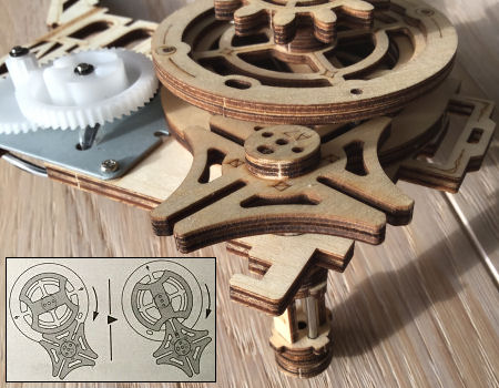
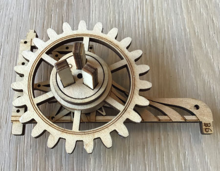
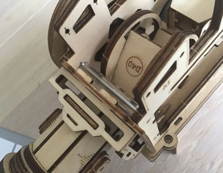
| Mounted here are the Maltese cross mechanism which also needs to be waxed for smooth movement, and on the other side of the sidewall on the same axis the sprocket with teeth that fit into the perforations of the film. These are the two parts that cause a intermittently movement of the film during showing. Check that the movement works properly (see insert). | No fewer than 22 parts are needed for the projection lens. Inside the lens tube is a sliding part with a plastic convex lens that can be moved with two buttons on the side to focus the projected image. Here again it became apparent with how much attention the instructions should be studied, because in this photo the buttons are not located on the side as they should. Fortunately, this was detected in time and could still be corrected at this stage. |
 |
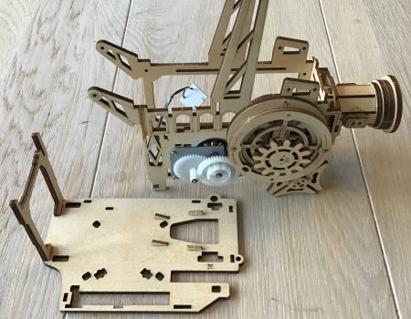 |
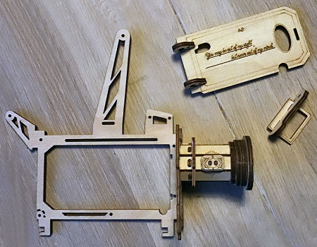
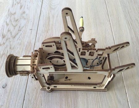
| The projection lens mounted on the second side wall, along with some pre-assembled parts that will be used later. | The two side walls are joined here. It all still feels a bit unsteady, but that gets a lot better when this assembly is mounted on the floorboard. The back wall is also mounted on this shelf. |
 |
 |
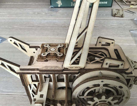
| Here we see how the two side walls, the rear wall and the front wall with the projection lens are mounted on the floorboard. As a result, the whole has immediately obtained much more sturdiness. |
Again this composition, now photographed from a different
angle. Here we clearly see the LED light that is connected to the dynamo with two wires. It still hangs loose. |
 |
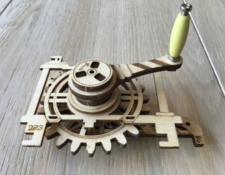 |
| Now the part with the crank and the gear that has to engage in another gear is put together. It is also important to carefully study the instructions for this stage. | This part is completed by placing the crank. The handle is one of the few parts that are not made of wood. The correct placement of the supports B6 and D23 is important here. |
| Then comes the section that can safely be called the most difficult part of the assembly. You actually need at least four hands for it. Enlist the help of an assistant! | |
 |
 |
| The crank part must now be secured to the floorboard, but in such a way that the round part at the back correctly engages the plastic gear of the dynamo. At the same time, the two support plates must also be attached to the base plate. A difficult task, but if it is done successful, the structure has already become a fairly stable whole. Relax! The assistant can go home again. |
If the foregoing is not done
properly, the projector may not work properly when it is finished and repairing
the error will be virtually impossible. Check carefully whether the crank can rotate freely and whether the Maltese cross is turned intermittently. We should now also see the LED light up brightly. |
 |
 |
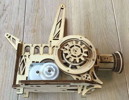
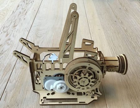
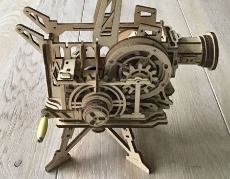
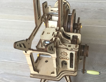
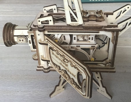
| After assembling some small parts that give the construction even more strength, the whole is provided with legs. Behind the large wheel you can just see the shutter inside that has to interrupt the light beam when the film is transported. | Then the light box with the LED light is assembled and mounted in place. When the crank is now turned, a light beam will already be projected through the lens. That beam of light is continuously interrupted by the rotating shutter. |
 |
 |
| The revolving shutter that regularly interrupts the light beam during film transport. Here we also see one of the plastic rollers on which the film is guided. | The shutter on the left and the light box on the right. A support plate is fitted and held in place with steel shafts and plastic shaft sleeves. |
 |
 |
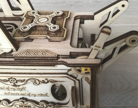
| One more look at the inside....... | ..... before the roof goes on. |
 |
 |
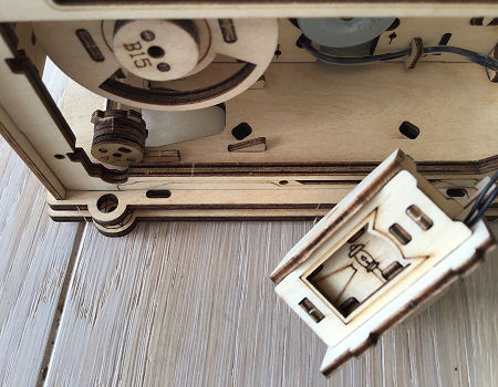
| A side door is fitted..... | ..... which can be closed with a lever. |
 |
 |
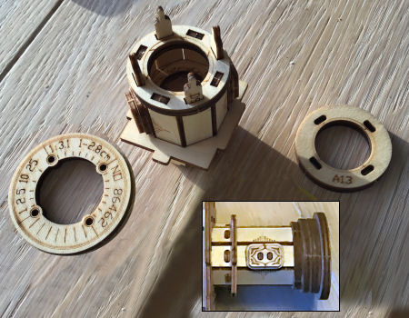
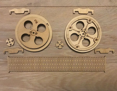
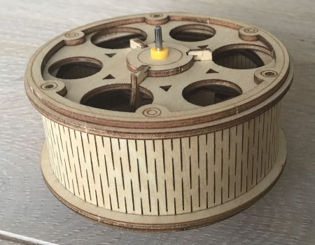
| These are the parts with which the two film reels are manufactured. The film track is made of very thin flexible bending wood. | The ends fit snugly together through the pins at the beginning and end that fit into a small cavity on the walls of the reel. |
 |
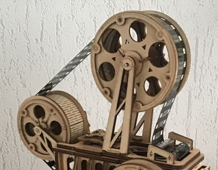 |
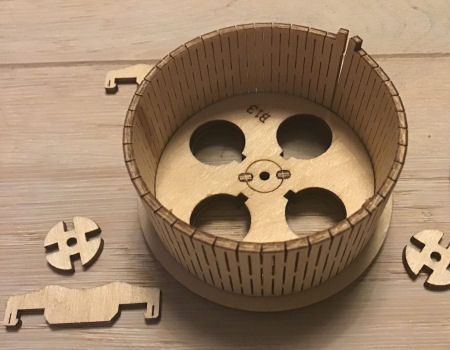
| The largest film reel completely assembled. Both film reels are put in place in the projector. | The film is inserted. The two ends are attached to each other with adhesive tape so that a loop is created. Just like with a real projector, care must be taken that the film images are upside down. |
 |
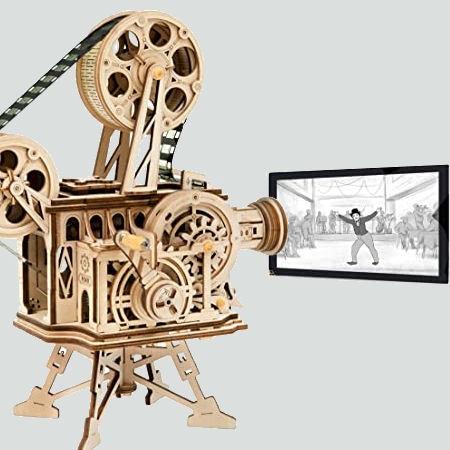 |
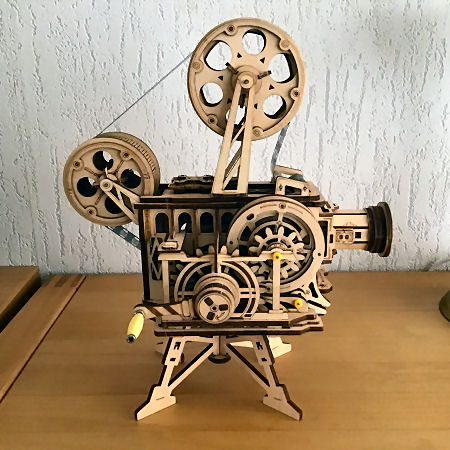
| The supreme moment. The projector is ready....... | ..... and yes..... it works! |
| Conclusion: It was a joy to assemble this projector. Wrong assembly is almost impossible if the manual is followed carefully. The operation of real film machines is very well imitated: the film transport with Maltese cross mechanism and sprocket, the rotary shutter, the focusing of the lens. An instructive and educational project that also produces a showpiece for the living room. This package is more than worth its money. | |
| |
©1997-2021 'de Luikerwaal' All rights reserved. Last update: 23-11-2021. |
|